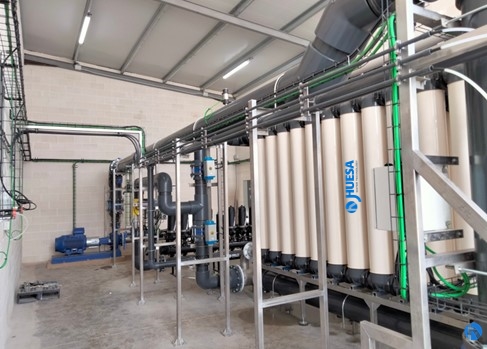
J. Huesa successfully completed the commissioning of a water treatment plant in an industry dedicated to the manufacture of cleaning products, detergents, capsules, and personal hygiene.
On this occasion, our client, a leading company in its sector, has relied on us to improve the quality of the feed water to its production process, and reduce production losses caused by stoppages in the existing water production plants in the factory.
Adopted solution
After analysing the raw water samples taken at different points in the production process, we were able to conclude that the feed water to the factory’s reverse osmosis system had a high content of colloids and suspended solids.
At this point, the technical department of J. Huesa opted for the design and manufacture, to measure, of a water treatment plant based on ultrafiltration membrane technology as a central element, whose objective is to clarify the water and reduce the content of colloids present in it, improving the quality of the water supply and reducing operating costs.
In addition, this solution guarantees suitable conditions for the reverse osmosis separation membranes, to extend their useful life and prevent clogging of the filtration pores, leading to membrane ruptures and recurrent production stoppages.
This treatment system, given the composition of the raw water and the nature of the particles present in the water, drastically reduces the fouling generated throughout the factory’s hydraulic system.
The installation under study is housed inside a building and consists of a pre-treatment stage comprising a self-cleaning ring filter system and a treatment stage using ultrafiltration membranes.
The ultrafiltration membrane system is equipped with automated cleaning for the correct operation of the plant, which allows continuous operation of the plant, minimizing the plant’s operating costs.
| Flow rate UF | 120-130 m3/h |
| BW Flow rate | 380 m3 /h |
| Ultrafiltration conversion | 90 % |
| Working hours | 24 h/día |
| Raw water accumulation | 2 x 1.000 m3 |
| Treated water accumulation | 1.000 m3 |
| Used of treated water | Reverse osmosis input |
Pretreatment
The raw water to be treated is stored in two storage tanks of 1,000 m3 each. These tanks are equipped with a recirculation pump, the purpose of which is to homogenize the contents and inject 14% NaClO into the stored water, keeping the chlorine level at around 0.8 ppm.
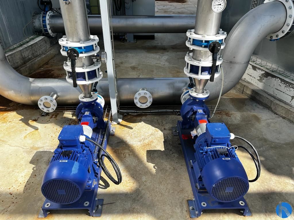
Detail of pumping groups
To reduce the entry of suspended particles into the ultrafiltration plant, in a previous stage, and as an additional screening, the water is pumped to a battery of ring filters equipped with a controller and automatic cleaning by means of compressed air with a filtering capacity of 50 microns.
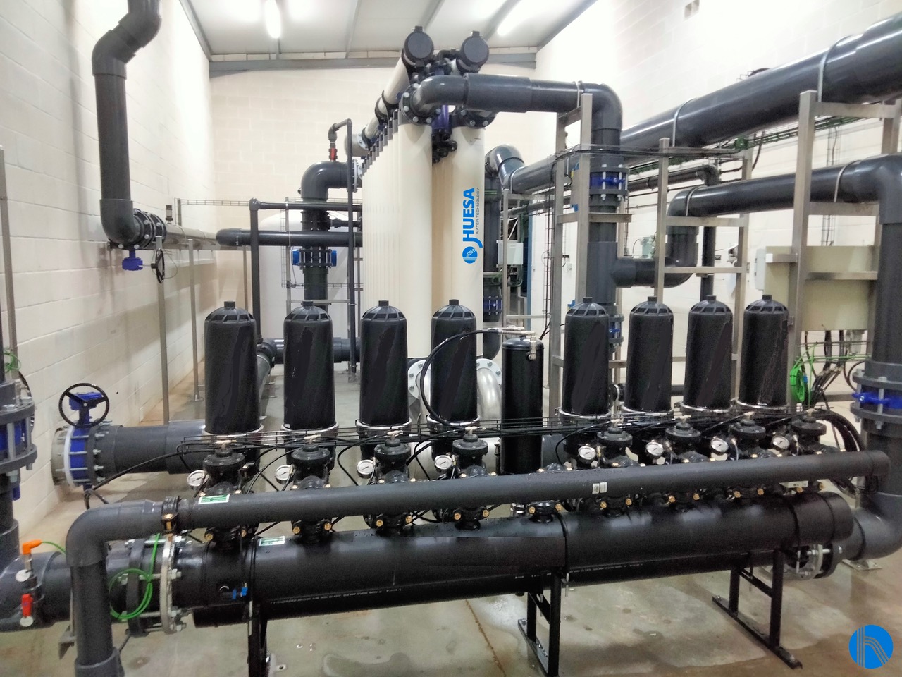
Detail of ring filter battery
Ultrafiltration System
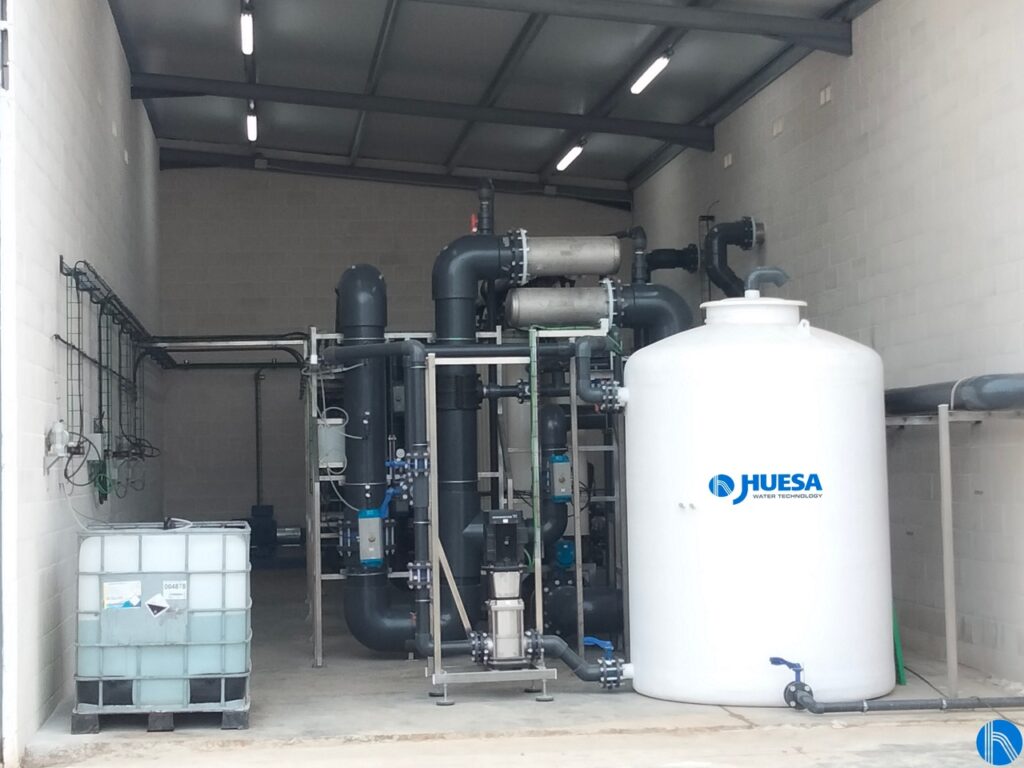
Ultrafiltration hall View
The water is then passed to the ultrafiltration membranes with a plant design flow rate of 120-130 m3/h.
Ultrafiltration is a membrane separation process in which the two phases in contact with the membrane are liquid and are at different hydrostatic pressures, with certain components being transferred to the low-pressure side.
Small particles dissolved in the liquid pass through the membrane, while larger molecules dissolved above 0.02 𝜇𝑚, colloids, suspended solids, algae and microorganisms such as bacteria, which do not pass through the pores, are retained.
The required pressure differences are quite low, as there are hardly any osmotic differences.
The ultrafiltration process is mainly used as a pretreatment for surface water, seawater, groundwater, biologically treated effluents and as a pretreatment of water for subsequent treatment with membrane demineralization technologies such as nanofiltration or reverse osmosis, as is the case here.
Ultrafiltration is classified according to the type of membrane used, and the choice of membrane will depend on the nature of the water to be treated and the size of the particles present in the water.
In this project, hollow fibre membranes are used, with a porosity of 0.02 𝜇𝑚 pitch, consisting of polyester sulphone tubes with holes through which the water enters with a diameter of 0.9 mm.
The hollow fibre membranes are inserted in tubular pressure modules through which the water circulates, alternating the entry of raw water through the lower or upper collector and obtaining a permeate of ultrafiltered water through tubes connected to the body of the modules.
For the maintenance of the modules, a rinsing process is carried out in the normal flow direction (FWF), performing an internal cleaning and a backwashing process (BW) from the outside to the inside with a higher flow rate.
The permeate from the ultrafiltration plant will go to a 1,000 m3 buffer tank.
CEB cleaning system
A CEB chemical cleaning process will be carried out from time to time, with an injection flow of 220 m3/h. This cleaning will consist of a backwashing process with chemical injection, after which the system will be left to soak for a shock time, and then the system will be rinsed until the chemical remains are eliminated.
After the shock time has elapsed, the system shall be rinsed for 90 seconds, pouring the contents into the drain until it is observed that there is no foam, and the pH recovers the normal operating values.
A chemical washing sequence will be carried out with NaOH 50% + NaClO 14% first, followed by an acid washing sequence with HCl 33%.
The water that we call rejection water in this process will be obtained because of the automatic cyclic washing processes of the system to eliminate the elements trapped inside and outside the membrane.
CIP cleaning system
The CIP chemical cleaning sequence is carried out after a complete washing sequence, using an alkaline or acidic chemical solution depending on the type of fouling expected.
This process is carried out manually periodically every 6 months or more, as a form of preventive maintenance, recovering the membranes and removing any residues that may have been trapped, returning the membranes to their original state.
Instrumentation and control
The water treatment plant is equipped with instrumentation and control elements (automatic valves, pressure switches, pressure transmitters, flow meters, conductivity, and pH meters…) which communicate with the programmable logic controller (PLC), included in the control and command panel.
The control panel also includes a touch screen for the operation and configuration of the plant. J. Huesa’s Instrumentation and Control team has designed the control panel so that it can be integrated into the customer’s SCADA system. In addition, it includes a remote-control system, allowing us to access and monitor the evolution of the plant, being able to act remotely.
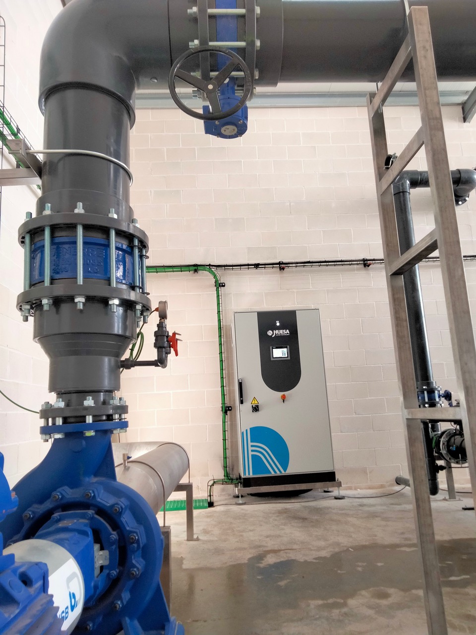
Control panel view

