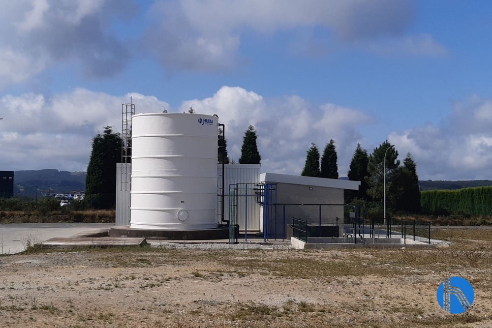
We are pleased to share a new success case of J. Huesa, in which we have carried out the turnkey project of WWTP for a leading multinational company in the production and supply of OMEGA 3 products that recently opened a new production center located in Galicia.
The success of this project lies in the close collaboration between the two companies. Aiming to obtain a proper design, a pilot laboratory test has been carried out in the first phase where operation parameters were defining allowing the characterization of the industrial process wastewater treatment plant.
Some of the key aspects of this project are detailed below.
Effluent characterization and plant design parameters
The aim of the test was to identify the appropriate physical-chemical treatment to reduce the FOG, AGS, suspended solids and phosphorus levels in two samples obtained from the mixture of three types of effluent provided by our client, the main difference being the presence or absence of phosphorus.
In order to characterize the industrial process water and carry out the most suitable design of the WWTP, it has been analyzed different samples provided by the client and has been done different Jar-Test in order to stablish the optimum chemicals dosage and chemical product types.
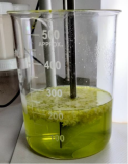
One of the tests performed in the laboratory
For choosing the design data, it has been considered data obtained from laboratory results considering both process alternatives (with phosphorous and without it). Design data has been established as the average of the different samples studied plus a security factor.
After carrying out the tests and taking into account the data provided by our client and the fact that the quality of the treated water must comply with the limits for discharge into the public sewerage system established in the Official Gazette of the Province of A Coruña D.L.: C-1-1958, J. Huesa’s technical team opted for the construction of a WWTP made up of the following sub-processes:
-
-
- Pretreatment
- Physical – chemical DAF type
- MBR (Membrane Biological Reactor)
- Sludge Treatment
-
| Nominal Flow Rate | m³/h | m³/day |
|---|---|---|
| Flow from process | 0,625 | 15 |
| Flow from CIP (*) | 0,098 | 2,35 |
| Total inflow from WWTP | 0,723 | 17,35 |
Total Design datal
(*) The CIP flow has been calculated taking into account 2 m3 per day of flushing and 21 m3/h per week for 5 minutes.
Adopted Solution
Pretreatment
In the first stage, it was identified the requirement of building a new pump sump that will be used as a homogenization basin and phosphorous-free reduction chamber and will treat part of the effluents before being mixed with another part of the effluents in order to optimize the chemical treatments required downstream.
This chamber was designed with a useful volume of 27 m3 and the following elements were installed in it:
- Grafting rate at the inlet of the pit in order to retain the coarse solids that are not treated and could damage other elements of the plant.
- Floatation and mixing agitation system, designed to agitate grease and a thick layer of floating sludge, allowing the contents of the pit to be mixed.
- pH measurement and control sensors.
- Submersible pump to feed the physical-chemical, the next sub-process of the WWTP.
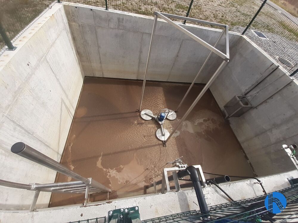
Homogenization chamber view
As this chamber will receive water from a high temperature process, it will also allow us to temper the fluid before it reaches the biological treatment plant.
Physical – chemical type DAF
Due to the high levels of suspended solids and oils and fats in the raw water, the technical team decided to install a DAF-type physicochemical unit as a pre-treatment to the MBR because these kinds of components are difficult to biodegrade.
This system reduces the load entering the biological treatment and facilitates the phosphorus elimination processes.
The process consists of three stages: coagulation, neutralization and flocculation. All stages take place in a system of interconnected tanks.
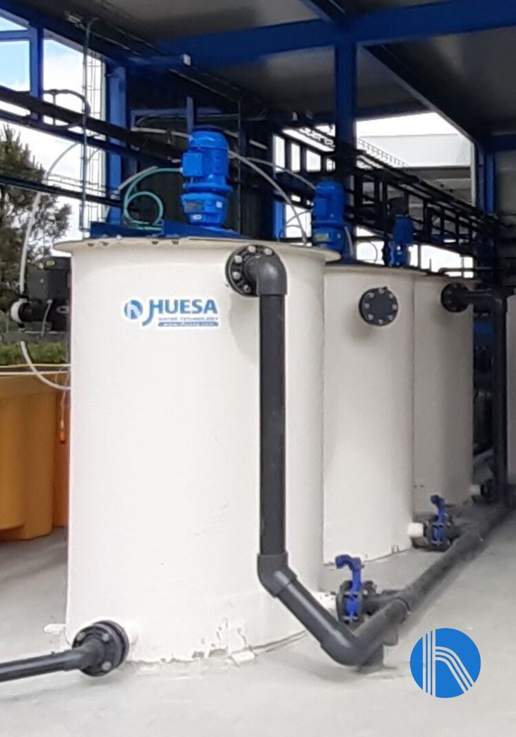
View of coagulation, neutralization and flocculation chambers
In the flotation process, air bubbles are artificially attached to the solid particles. This gives the particle-gas assembly a very high upward velocity. The system also allows particle-gas agglomerates to form clusters, which, like clusters, form assemblies that double the initial ascending velocity. The result is rapid removal of the solids load.
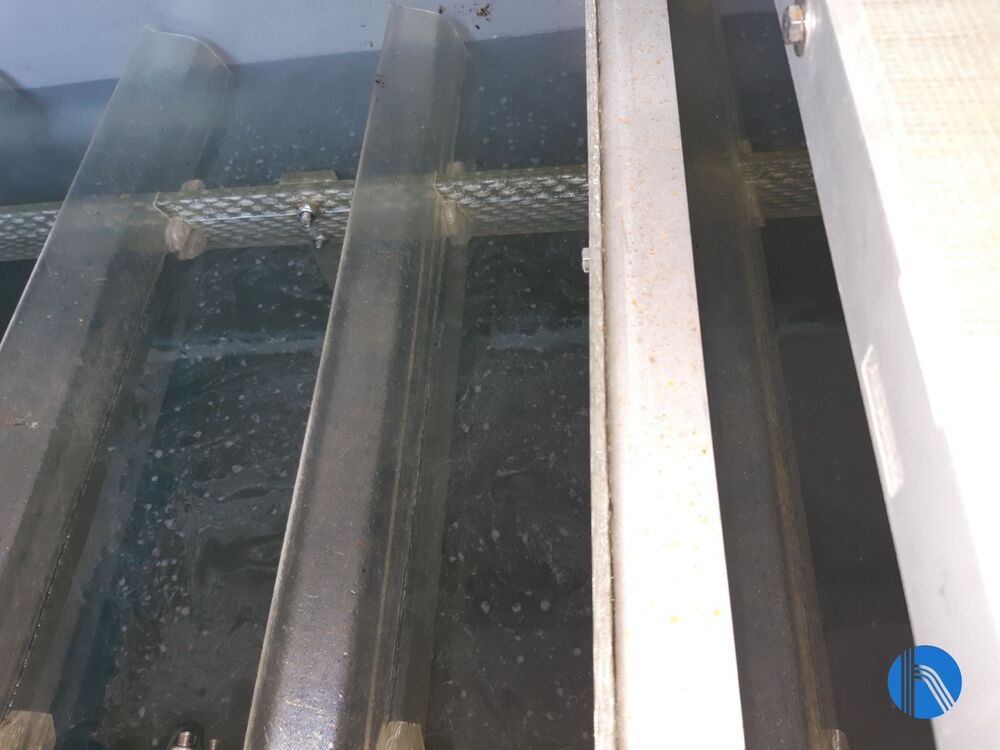
Float in operation
MBR biological treatment
Our client’s effluent requires drastic removal of the organic load to comply with the treated water requirements. Most economical and efficient alternative, assuming a biodegradable organic load, is biological treatment.
In this case, membrane bioreactor (MBR) treatment was chosen as the water is ultra-filtered and therefore treated water requirements are reached, and it could discharge to a public watercourse.
External tubular clarification membranes, which are the most robust of the MBR type solutions, were chosen due to the high variability in the nature of the effluent.
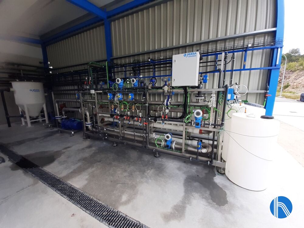
Tubular ultrafiltration plant view
The raw water is deficient in nutrients, so the biological reactor has equipment for preparation and dosing of nutrients, as well as the dosing of antifouling to prevent the formation of foam.
The oxygen required for the biological process to run satisfactorily is supplied by means of rotary piston blowers, the air in the reactor being distributed by means of a grid of diffusers, which allows us to supply the air by creating a fine bubble that improves the transfer of oxygen.
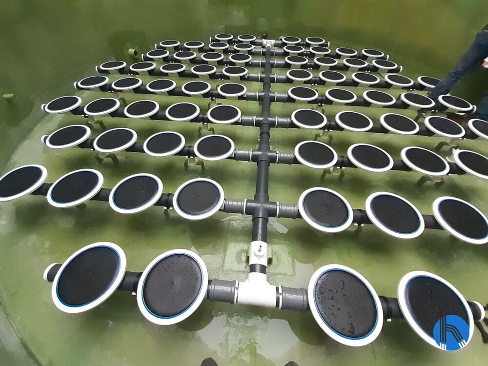
View of the diffuser grid. Biological reactor
Sludge Treatment
As the reactor evolves, the biological material inside it increases. To keep the bacterial population in the reactor under control, a sludge washing system has been implemented.
The purified sludge is sent to a civil engineering pit where it is kept in motion to prevent sedimentation. Once the sludge has been homogenized, it is sent via a submersible pump through a sludge dewatering unit.
The sludge is pumped to the dewatering equipment and conditioned by the addition of polyelectrolyte to promote separation on a sludge dewatering screw.
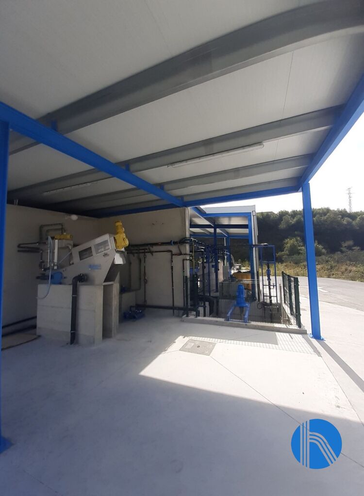
View of sludge dewatering screw
The operation of the plant consists of a flocculation chamber into which the sludge is fed, followed by a filtration system. The sludge is dewatered in the filtration process, the water falls to the bottom of the unit, which is returned to the head of the WWTP, and the dewatered sludge exits at the rear for appropriate management.
Instrumentation and control
The entire operation of the system is controlled from the electrical panel, where the automaton that manages the installation is located, as well as the touch screen that we use to visualize and parameterize the various operating variables.

