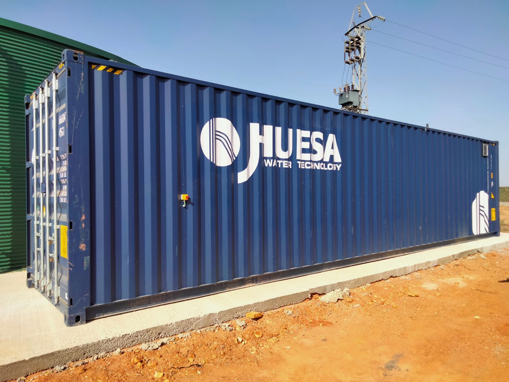
In conjunction with the 16th edition of Fruit Attraction, where Andalusia was the guest region, we would like to present a successful case study of a turnkey project executed for an Andalusian multinational company specializing in the production and marketing of red fruits on an international scale.
Data and water characteristics
The goal of this project is to provide a comprehensive solution for the removal of salinity and organic contamination from water sources. We have implemented a containerized reverse osmosis system that ensures the output water meets the highest quality standards and optimizes fertigation performance.
Following an initial assessment of the water conditions, the technical team at J. Huesa has selected the production of a containerized plant housed within a 40′ High Cube container, capable of delivering a daily output of 1,210 m³.
| Flux J. Huesa´s WTP | |
| Input Flow rate WTP PTA | 73,3 m3/h |
| Production Flow RO | 55 m3/h |
| RO rejection flow | 18,33 m3/h |
| RO conversion | 75 % |
| Working hours | 20 h/d |
| Total daily production Flow rate | 1.210 m3/h |
| Raw water accumulatoion | 60 m3 |
| Treated water accumulation | Basin |
| Used of treated water | Irrigation |
Adopted solution
J. Huesa has devised a solution that aligns with the technical objectives of the client and the overarching goals of the project. The water treatment plant will comprise the following treatment train:
- Pretreatment.
- Reverse osmosis.
- Cleaning-in-place system (CIP)
- Instrumentation and control system
- Pretreatment
In the initial stage, the water from the raw water accumulation tank is pumped to a battery of two low-speed, automatic washing bilayer filters. This process allows for the retention of any suspended solids that may be present in the water from the well.
To prevent the formation of biological activity inside the equipment, a sodium hypochlorite injection/dosing system has been incorporated at the inlet of the filters. In normal operation, both filters will be in service, with the flow divided symmetrically.
The filters are equipped with a system of independent valves to facilitate the washing of the filters. The valves are operated automatically and are managed by the automaton located in the control panel included in the reverse osmosis system container.
The cleaning process, which consists of two stages (backwashing and settling), is carried out according to a set schedule, considering the maximum pressure loss in the water line between the inlet and outlet.
Once one of the filters requests cleaning, production is stopped and both filters are cleaned sequentially, first one, then the other. Once the cleaning process is completed, production begins again.
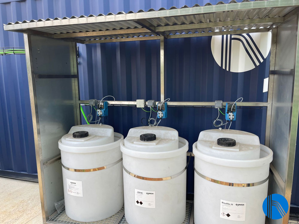
View dosing skid
Reverse Osmosis System
The next stage of the WTP treatment process is reverse osmosis. However, to ensure the long-term effectiveness of the osmosis membranes, a pre-treatment dosage is carried out before the water enters the pressure pipes.
An antiscalant is added to prevent the formation of saline incrustations in the membranes. A sequestrant (bisulphite 25) is also included to facilitate the conversion of the chlorine present in the water to its hypochlorite form, which was previously achieved through the addition of hypochlorite in the previous stage of the treatment process.
The pre-treated water is then transferred to the reverse osmosis module, where it is initially filtered through 5-micron pore-size cartridges. This process ensures the retention of any potential leaks of very small particles, including suspended solids and colloids.
The safety filter comprises replaceable 5-micron cartridges, which are managed by means of a pressure difference measured by two pressure gauges placed at the inlet and outlet of the filter. The frequency of cartridge replacement will depend on the colloid content of the water.
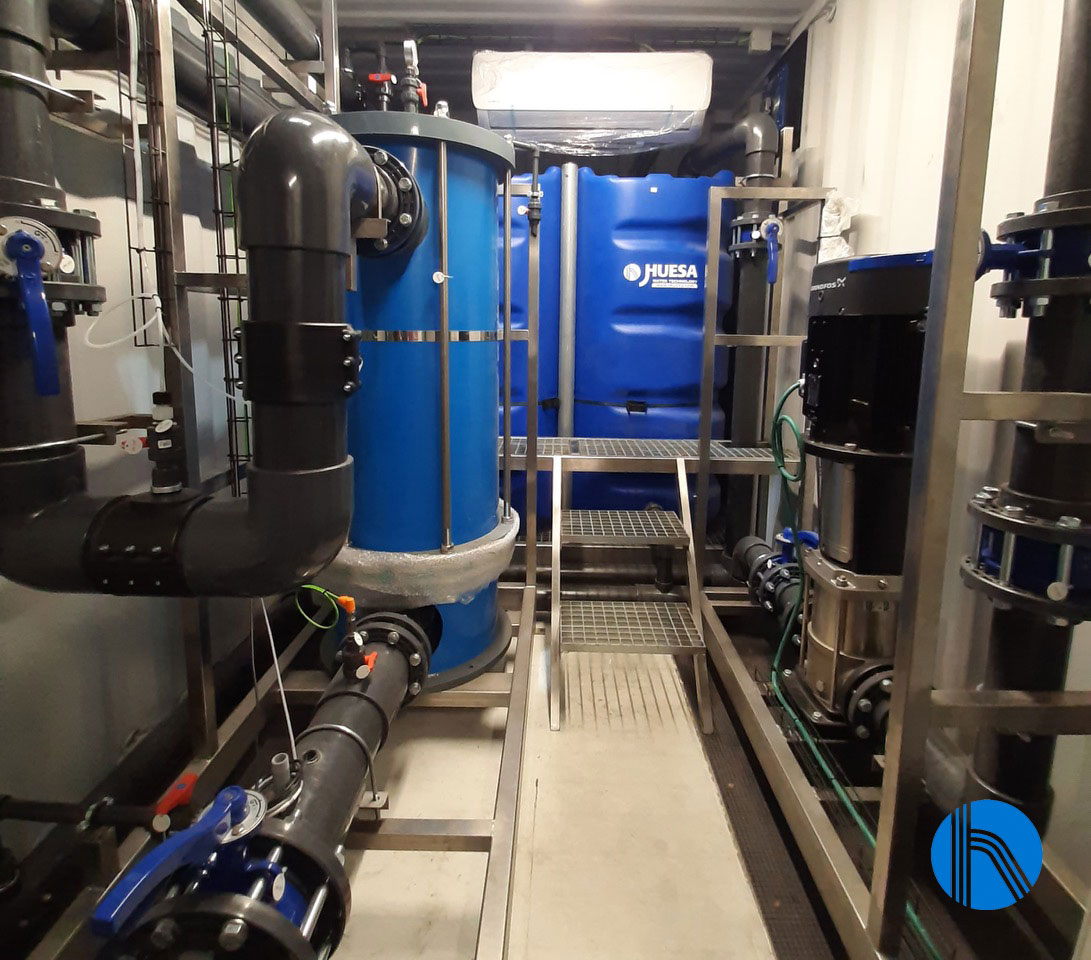
Safety pre-filter and view of the cleaning system
The osmotic pressure is obtained using a high-pressure vertical centrifugal pump manufactured from AISI 316 stainless steel. Its function is to maintain a constant osmosis inlet pressure, utilizing a control loop comprising a pressure transmitter and a frequency inverter.
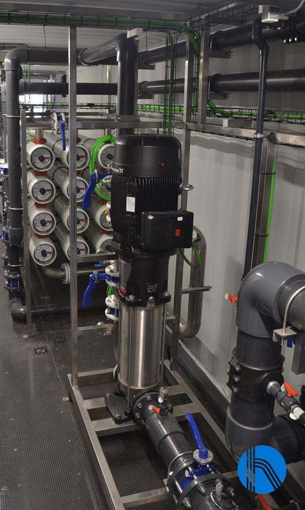
High-pressure pump
The installation will be fitted with spiral-wound membranes, made of polyamide and specially designed for brackish water up to 8000 ppm, which are capable of operating at low pressure. The membranes are mounted in the same pressure housing, which is made of GRP.
These membranes have a high chemical resistance, operating effectively in a pH range of 2 to 13. This makes them simple to wash and recover, as they accept a wide variety of washing chemicals.
For monovalent ions, the separation selectivity is between 90 and 95 %. For divalent ions, the selectivity is over 98 %. For mineral or organic colloids, bacteria and viruses, this selectivity reaches 99.9 %.
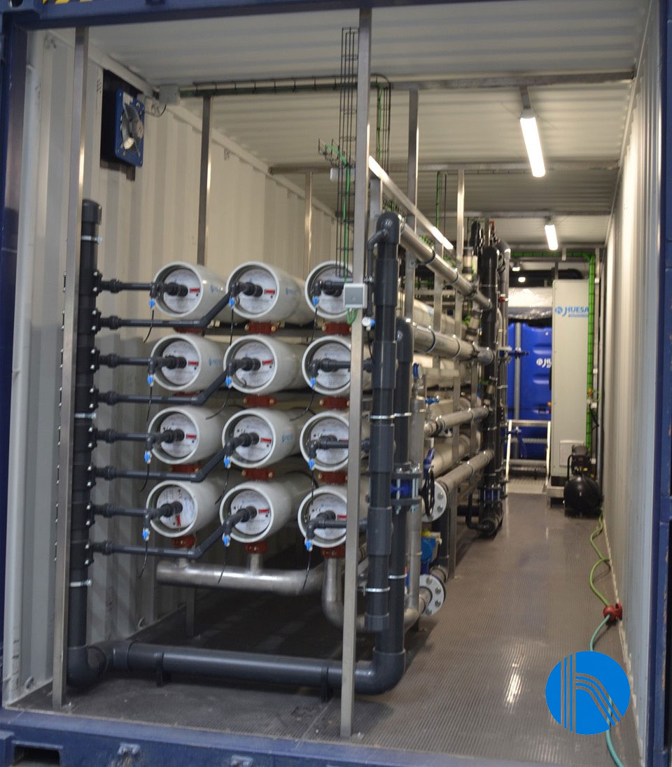
View reverse osmosis housings
Cleaning in place system (CIP)
It is inevitable that all membrane installations will become fouled over time, depending on the pre-treatment installed. The extent of fouling will vary, but one to two cleanings per year will be required.
A chemical cleaning or CIP system has been installed in the reverse osmosis skid. This comprises a reagent preparation tank, a stainless-steel recirculation pump and stainless steel stage isolation and recirculation valves. The filling of this tank is automatic, thanks to a float valve connected to the same osmosis water line.
- The system is equipped with two pumps, which have the following advantages:
- The higher-power pump is ideal for supplying the osmosis plant.
The pump with the lower installed power is used for flushing and chemical cleaning of the membranes.
Instrumentation and control
The water treatment plant is equipped with a range of instrumentation and control elements, including automatic valves, pressure switches, pressure transmitters, flow meters, conductivity and pH meters, which communicate with the programmable logic controller (PLC) included in the control and command panel.
The control panel also includes a touch screen for the operation and configuration of the plant. J. Huesa’s Instrumentation and Control team has designed the control panel to be integrated into the client’s SCADA system. Furthermore, it includes a remote-control system, allowing remote access and monitoring of the plant’s status and enabling remote action.
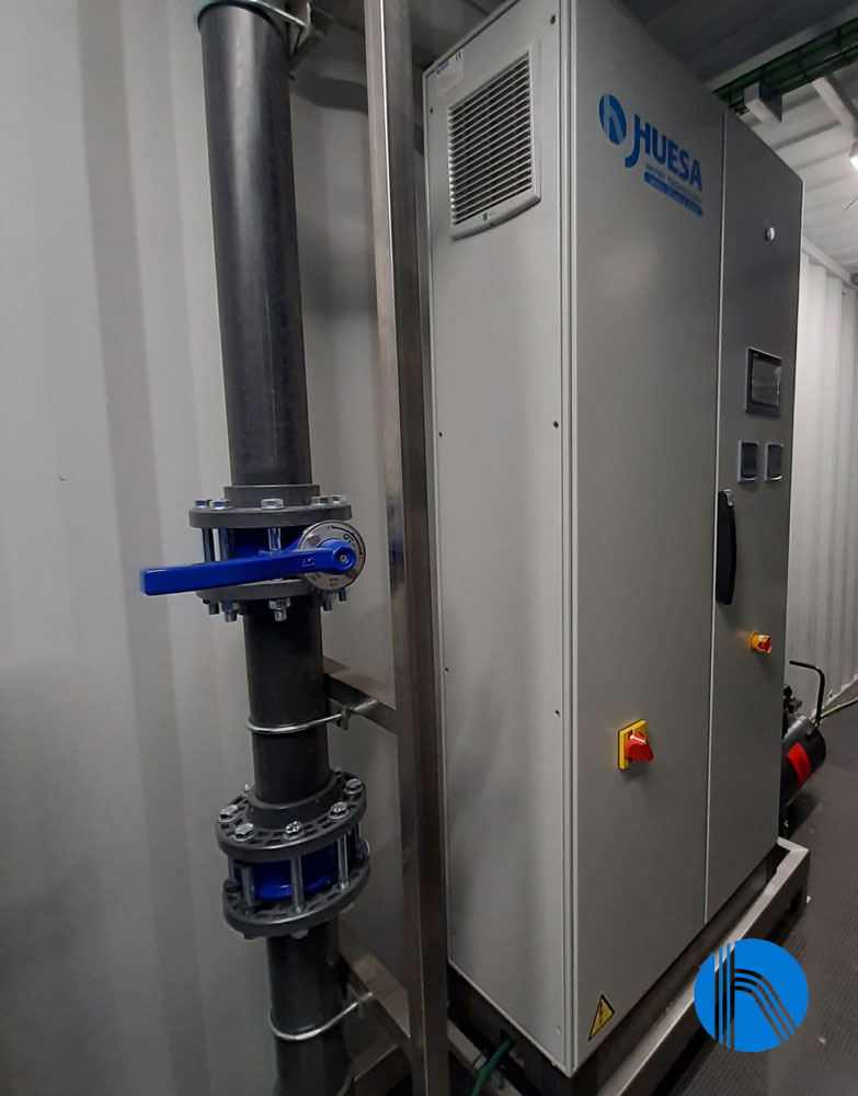
Electrical control panel
Technical Assistance Service
Our company provides specialized technical attention to ensure optimal performance and reliability of our clients’ equipment.
To fulfil our commitment to our client, the after-sales department of J. Huesa, which specialises in the operation and maintenance of water treatment installations, is conducting the scheduled preventive maintenance of this water treatment plant. This maintenance is designed to optimise the plant’s technical, economic and environmental performance.
A maintenance plan is prepared for each installation, considering the specific requirements of the plant. This plan includes a schedule of scheduled visits, which in this case are carried out monthly.
During this visit, the technician will conduct a review of the key points of the installation and will perform the following activities with the objective of optimising the processes and ensuring the plant is kept up to date:
- General overhaul of the equipment.
- Chlorine measurement at the point of entry to the plant.
- The technician will verify the conductivity and redox probe measurements with multi-parameter equipment.
- Conductivity measurements will be taken in stages with multiparametric equipment.
- Inspection of the stops outside the plant and testing of the flushing pump in manual mode.
- Opening of the safety filter and replacement of the PX05-40 cartridges.
- Opening of the ring filters. A manual backwash cycle is forced, with a subsequent check to ensure it is carried out correctly.
Regulation of the mixing flow to achieve the required conductivity. - Checking the product dosing pumps and the state of their valves, which are found to be correct.
- Data collection and completion of the maintenance range.
- Drawing up the corresponding report.

