J. Huesa completed the commissioning of two of the treatment lines which make up the industrial wastewater treatment plant of the new Integral Treatment Centre for Non-Hazardous Industrial Waste (CTRINOP) in Abajas, in the province of Burgos.
This project, which has been declared of regional interest by the Junta de Castilla y León, is to be carried out in six phases and will make it possible to treat different flows of water which are sized for an expected flow of more than 55 m3/day, from:
- Leachate from the non-hazardous waste deposit at the Treatment Centre,
- Rainwater and faecal water originating at the centre itself,
- And, finally, organic liquids of low and high pollutant load, from non-hazardous industrial discharges.
On this occasion, the Technical Department of J. Huesa has opted for the implementation of a set of technologies that allow the treatment of very different types of water, so that depending on the characteristics of the raw water and, considering the discharge limits, the water to be treated will follow one treatment or another.
Low Load Line
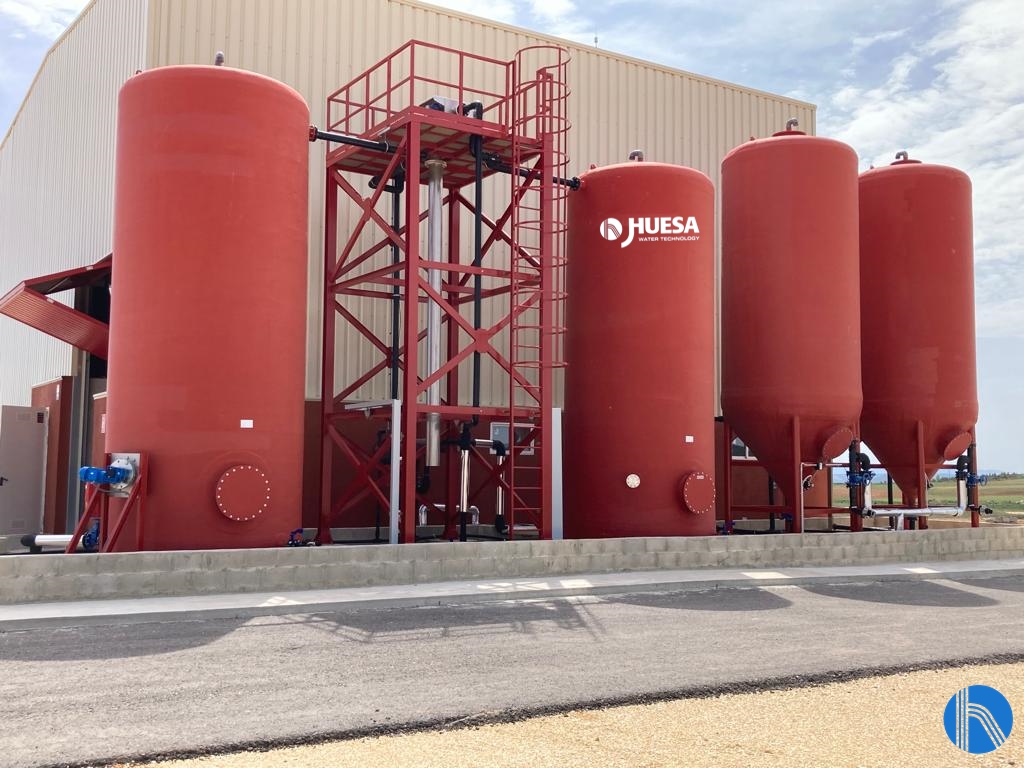
View of storage and homogenization tanks
Firstly, we will describe the low load line which, as its name suggests, will be used to treat water with a low pollutant load. It will also be used as a pre-treatment for high load discharges with a high content of suspended solids and oils and fats.
The equipment that makes up this treatment line is detailed below:
Depending on the origin of the low pollutant load discharge, it can reach the line in two different ways:
- When they correspond to discharges produced in the landfill, they pass directly to the rotating screen.
- When they come from outside, in an initial stage they are stored in a conical bottom tank equipped with all the truck-tank connection elements.
In both cases, the screened water is accumulated in a GRP tank equipped with agitation to prevent the particles in suspension from settling. We refer to the tank on the left in the image above.
The rotating screen is a self-cleaning device capable of operating for long periods of time without the need for attention.
The liquid to be filtered enters the rotary sieve through the inlet pipe and is evenly distributed over the entire length of the filter cylinder, which rotates at low speed. The solid particles are retained on the surface of the screen and are conveyed to the scraper, which is responsible for separating them and depositing them on an inclined tray to fall by gravity.
Physical – Chemical DAF type
The effluent then enters the next stage of treatment, the DAF (Dissolved Air Flotation) type physical-chemical treatment. To ensure the separation of solids in the flotation chamber, the waste passes through the coagulation and flocculation chambers (made of GRP and equipped with the necessary agitation), where the coagulation and flocculation process is carried out by injecting coagulant and flocculant, on the one hand, and soda for pH control, on the other.
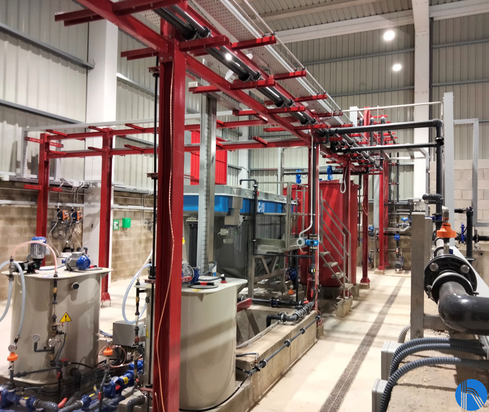
DAF plantview
Once it enters the DAF, and thanks to the laminar regime and the effect of the micro-bubbles that are injected into it together with the discharge at the inlet, the floccules formed in the previous stage rise to the surface, forming the sludge and leaving the clarified water free of solid particles. There are scrapers on the surface of the DAF that remove the sludge and remove it from the equipment.

View of the centrifugal decanter
The treated effluent will be sent to the storage pond, from where it will be treated in the biological line which is to be installed when the landfill is 100 % operational.
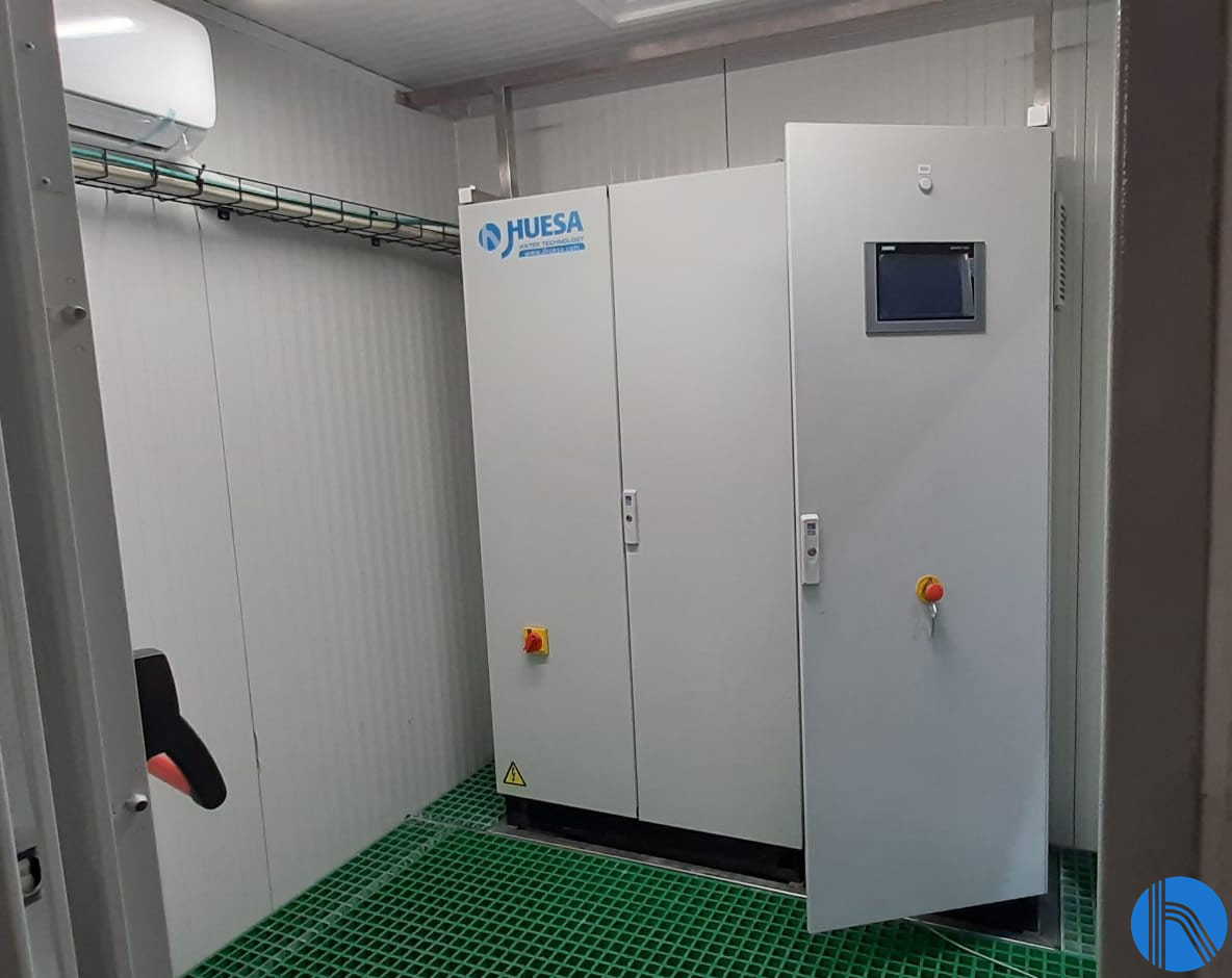
This installation is equipped with an electrical control panel with a programmable logic controller and a touch screen for the operation and configuration of the plant. J. Huesa Instrumentation and Control team has designed the control panel so that it can be integrated into the client’s SCADA system.

EC View
High Load Line
As with low load discharges, high pollutant load discharges can have a double origin:
- Those generated at the landfill itself are pumped from the leachate pond to the rotary screen, where the larger solids are removed. The output from the screen goes directly to the 25 m3 capacity GRP homogenization tank.
- As with the low-load discharges, the high-load discharges from the outside are initially stored in a conical bottom tank equipped with all the truck-tank connection elements. From this tank they are pumped to the rotary sieve to finally end up in the homogenization tank (tank located to the right of the sieve structure in the image above).
The homogenisation tank is equipped with a recirculation pump with a double function:
- To keep the discharge agitated while dosing sulphuric acid (H2SO4).
- To carry out a pH control thanks to the phmeter inserted in this recirculation line.
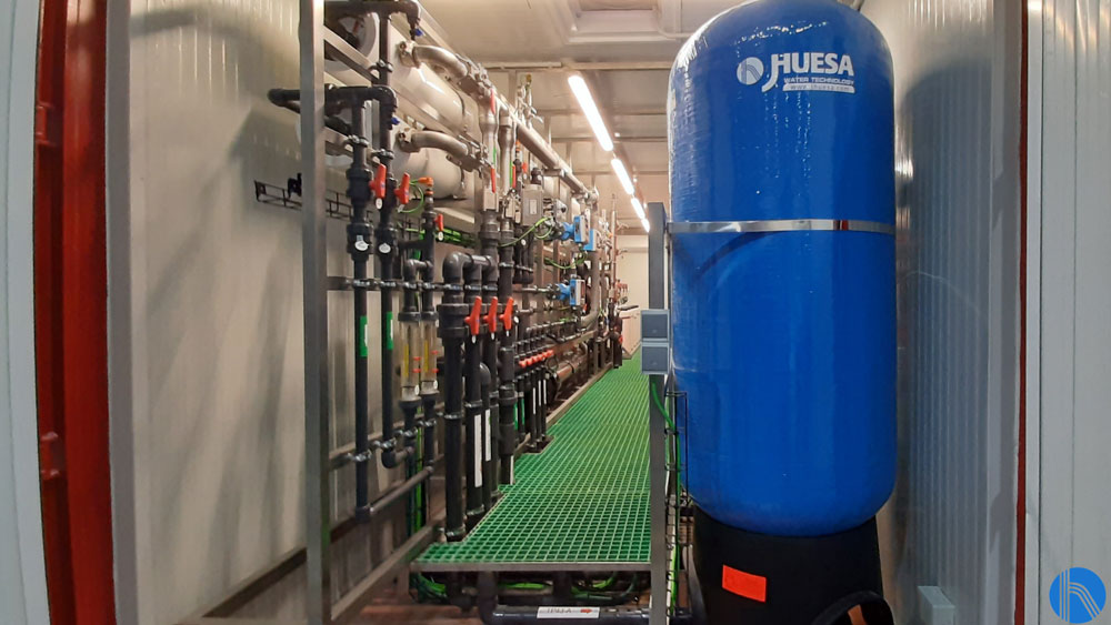
It should be noted that having a slightly acidic pH at this point is important and significantly improves the performance of the reverse osmosis system which is located inside a 40″ High Cube container.
Pretreatment
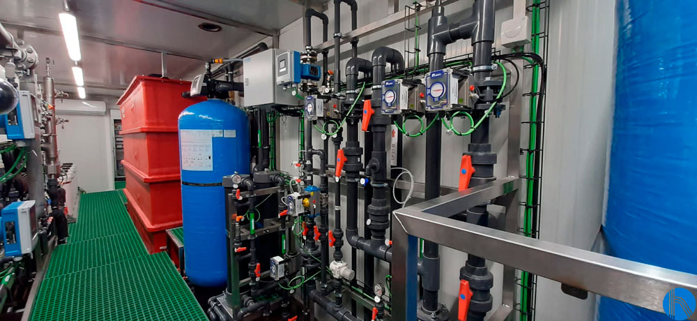
The water is then pumped into a low-speed, automatic backwashing two-layer filter where any suspended solids in the raw water are retained.
Specifically, the filter is made of glass fibre reinforced polyester (GRP), with a diameter of 762 mm and a nominal flow rate of 3 m³ /hour. It is equipped with a system of independent valves to carry out the filter cleaning operation. This cleaning process consists of two stages: backwashing and settling.
The operation of the valves is automatic and is managed by the automaton located in the control panel included in the osmosis frame. The production of filtered water is interrupted when the filter requests cleaning, which may be due to time in service hours and/or pressure difference detected between the inlet and outlet.
Chemical products are then dosed, specifically biocide and sequestering and anti-fouling products with the aim of preventing membrane fouling and extending the useful life of the reverse osmosis membranes.
Reverse Osmosis
| Raw water | 3 m3/h |
| Pipe feed | 40 m3/h |
| Recirculatedconcentrate | 37 m3/h |
| RO Conversion | 65 % |
| Workinghours | 24 h/day |
| Use oftretatedwater | Discharge |
Considering the pollutant load of the raw water, reverse osmosis is characterized by the fact that it must work with high pressures in order to treat the water correctly.
The pre-treated water is passed to the reverse osmosis system, which is preceded by two safety pre-filters, one of 10 microns and the other of 5 microns, in which possible particle and SS leaks are retained. Once the water is ready, it is pumped by means of a high-pressure AISI 316 stainless steel piston pump with a capacity of 8 m3/h and capable of providing a maximum pressure of approximately 60 bar.
The reverse osmosis system is configured in a single stage, consisting of two pressure tubes each containing 5 membranes, achieving a conversion rate of around 65 %. To ensure sufficient pressure supply, the system has been designed with a recirculation of 37 m3/h, so that 40 m3 per hour enter the plant.
The installation is provided with spiral wound membranes, made of polyamide, and specially designed for water and with the characteristic of working at high pressure, high flow and resistant to fouling. They are mounted in pressure housings made of coiled GRP.
A flushing – CIP system has been installed in the container, which guarantees the automatic cleaning of the membranes inside the tube. These cleanings are programmed from the touch screen, according to the needs of the operators and/or each time the plant is stopped.
Additionally, a chemical cleaning or CIP system has been incorporated, which is produced semi-automatically when required by the client, depending on the production requirements.
Vista flushing – CIP
The reverse osmosis plant is equipped with instrumentation and control elements (automatic valves, pressure switches, pressure transmitters, flow meters, conductivity, and pH meters…) which are centralized in an electrical panel, located in the container.
The panel also includes a programmable logic controller and a touch screen for the operation and configuration of the plant. J. Huesa Instrumentation and Control team has designed the control panel so that it can be integrated in the client’s SCADA system.
EC View