On this occasion, our client, a multinational technological leader in the execution of turnkey projects for
the production of renewable hydrogen by means of electrolysers, needed to incorporate an ultrapure water
production system prior to the electrolysis process for the production of hydrogen.
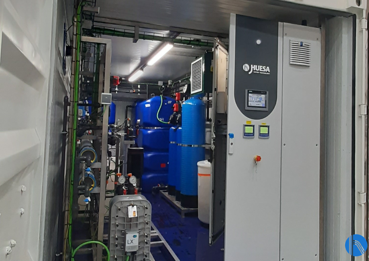
After analysing the conditions of the project and the specific needs of our client, the J. Huesa stechnical
team opted for the design and manufacture of a tailor-made demineralised water treatment plant inside a 20 feet container.
Adopted solution
The main data of the system implemented, consisting of a reverse osmosis system plus EDI preceded
by the corresponding pre-treatment, are detailed below.
| Raw water input flow rate | 0,89 m3 /h |
| RO input flow rate | 0,95 m3 /h |
| RO production conversion | 70% |
| RO production flow rate | 0,67 m3 /h |
| EDI input Flow rate | 0,67 m3 /h |
| EDI conversion | 90% |
| Production flow rate | 0,6 m3 /día |
| Working hours | 24 h/day |
| Used of treated water | Demi water for electrolyzer |
Table 1. Installation design data
In compliance with the characteristics of ultrapure water, it must also comply with:
| Conductivity | ≤0,1 µS/cm |
| TOC | ≤ 30 ppb |
The main components of the system are detailed below.
Pretreatment
The water from the mains is fed into a mesh filter consisting of a screen with a pore diameter of 25
microns, in which all suspended solids with a larger diameter are retained.
The water then passes through an activated carbon filter with a nominal flow rate of 0.89 m³/h in which
all organic contaminants are retained. This filter is equipped with an automatic chronometric valve that
performs automatic filter cleaning.
The filtered water is introduced into a decalcifier responsible for partially eliminating dissolved salts,
mainly calcium and magnesium, thanks to the action of a cationic resin contained in the bottles in order
to prevent these salts from precipitating in the osmosis system and causing incrustations in the
membranes that would result in poor quality permeated water.
The equipment installed has a « duplex » configuration, which allows one of the bottles to be regenerated while the other is automatically put into production, which increases the availability of the system.
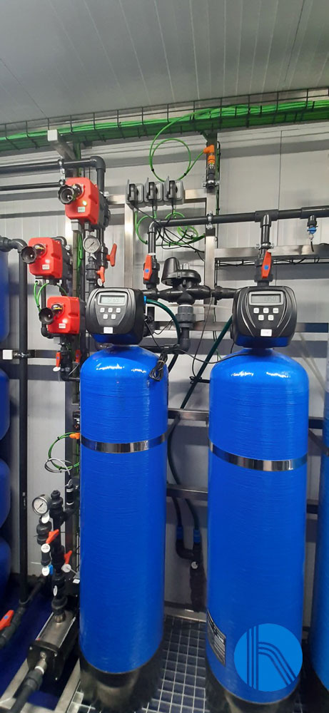
Picture 1. Duplex water softening system
The water is then accumulated in a tank with a capacity of one cubic metre from which it is pumped to
the reverse osmosis.
Prior to entering the reverse osmosis, a carbon dioxide elimination system has been contemplated, by
means of a NaOH dosing system. It is necessary to eliminate the CO2 present in the stream before the
permeate stream is introduced into the EDI system. To do this, the dosing of soda will convert the carbon dioxide present in the water into bicarbonate, which will be retained by the osmosis membranes.
Reverse Osmosis
Reverse osmosis is a process by which water is demineralised by pushing it under pressure through a
semi-permeable reverse osmosis membrane. A high-pressure pumping system is used to overcome
the osmotic pressure, thus forcing the salt-free water through the membrane and leaving a high
concentration of salts in the rejection flow. Osmosis membranes are characterised by high salt rejection
rates of around 95-99%.
This natural pressure plus the net pressure necessary to obtain the production flow (which is called
operating pressure) is obtained by using a vertical high-pressure centrifugal pump in AISI 316 stainless
steel with a nominal flow of 1.5 m3/h.
The system is equipped with spiral wound polyamide membranes specially designed for high salt
concentration water up to 8000 ppm. specially designed for water with a high salt concentration of up
to 8000 ppm. These membranes have high chemical resistance, they can work in a pH range of 2-13,
which makes them very easy to wash and recover. This makes them very easy to wash and recover,
admitting a variety of washing chemicals.
They are mounted in pressure housings, made of coiled GRP.
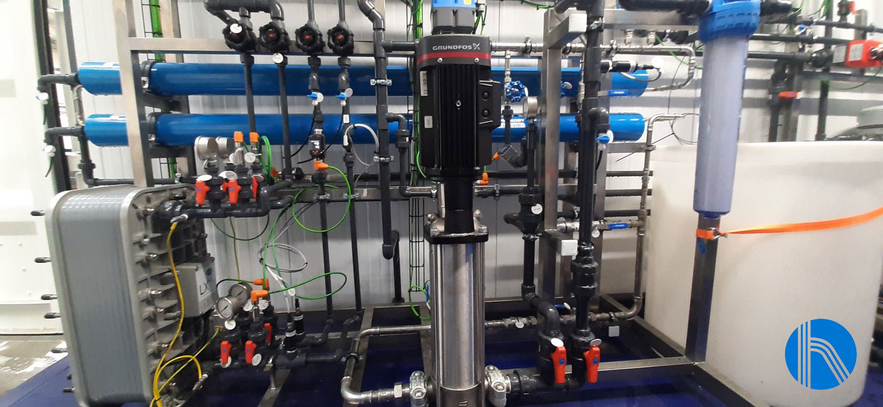
Picture 2. Reverse Osmosis system
The osmosis permeate is collected in an accumulation tank of 1000 litres capacity from where it is
pumped to the EDI through a pump with a nominal flow rate of 0.8 m3/h and ensures that the water
reaches the basin with the necessary pressure.
EDI System
The last step in the treatment line will be to subject the permeate water flow from the osmosis to an
electrodeionisation process, in order to obtain ultrapure water that meets the necessary requirements
of the hydrogen production electrolyser equipment.
EDI systems combine ion exchange with electrodialysis, achieving very high quality permeate. This is
possible thanks to the introduction of an exchange resin inside the compartments between the
membranes of the electrodialysis cells which, when current is applied, generates flows that drag the
cations towards the cathode and the anions towards the anode, achieving flows of concentrated water
and a flow of deionised water.
To reduce the consumption of mains water, the reject from the EDI is returned to the osmosis water
storage tank.

Picture 3. View EDI stack
CIP/flushing cleaning system
To ensure the maintenance of the reverse osmosis membranes and the EDI basin, the plant is equipped
with a 250-litre tank with a pump that drives the water for flushing both membranes.
Instrumentation and control
The water treatment plant is equipped with instrumentation and control elements (automatic valves,
pressure switches, pressure transmitters, flow meters, conductivity and pH meters…) which
communicate with the programmable logic controller, included in the control panel, through IO-Link
technology.
The control panel also includes a touch screen for the operation and configuration of the plant. J.
Huesa’s Instrumentation and Control team has designed the control panel so that it can be integrated
into the customer’s SCADA system. It also includes a remote control system.