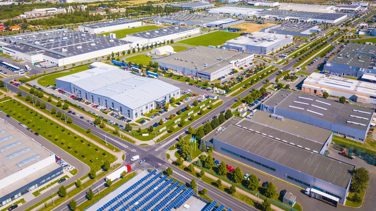
Today we share with you a project that we have executed for an important supermarket chain that, in its process of implementation in the neighboring country, has built a logistics block in Portugal.
On this occasion, our client, a leading company in the distribution of food products with more than 1,600 supermarkets distributed throughout the Peninsula, has resorted to the services of J. Huesa to solve the water management in the center located in Lisbon, which we detail below.
1. Stormwater management
The plot on which the new logistics center is located adjoins a series of agricultural plots that cannot be affected by changes in the flow of rainwater following the construction and operation of this new facility.
For this reason, our client contracted our services for the execution of the Rainwater Drainage Network, which has been designed following the specifications described in the study carried out for this purpose. This study was based on the hypothesis that the final destination of the water collected inside the plot would be to lead it to the water line that crosses the land, without any increase in flow after the construction of the platform.
Therefore, in order to avoid inconvenience to the downstream water line due to the increased flow resulting from the construction of the logistics platform, which would result in a higher level of waterproofing of the land and, consequently, an increase in the flow of rainwater generated inside the plot that would flow into the sewerage network in the same area, a solution was developed for the drainage of rainwater inside the plot based on the construction of 5 retention and flow lamination basins.
| Pond | Service area | Flow | Pump |
| 1 | Service Building | 207 m3/h | 1+ 1R |
| 2 | Refrigeration building | 990 m3/h | 1+ 1R |
| 3 | Dry Cleaning and Warehouse Buildings | 270 m3/h | 1+ 1R |
| 4 | Packing Building and surrounding area | 396 m3/h | 1+ 1R |
| 5 | Installations substation | 40 m3/h | 1+ 1R |
For the correct management of rainwater, J. Huesa has installed and commissioned, for each of the 5 ponds, a pumping system and collectors accompanied by their respective electrical and control panel, equipped with a programmable logic controller that will allow the remote control of the installation.

Image 1. Pumping well pond 5
2. Water Treatment Plant
The water supply for these installations is direct from the municipal mains water and is stored in 150 m3 tanks, with the aim of ensuring a continuous supply of water in the event of a water cut. In an initial phase, our client has envisaged 6 tanks with these characteristics, which can be extended to 3 more tanks in a second phase.
To comply with water quality legislation and guarantee optimum conditions for the water supply to the logistics block, it is necessary to design, manufacture, install and commission a disinfection skid consisting of a continuous chlorination system that guarantees the elimination of pathogens inside the storage tanks.
Water data and characteristics
Our equipment has been designed with the possible expansion of storage tanks in mind.
| Volume tanks | 9×150 m3 = 1.350 m3 |
| Nº of tanks | 9 |
| Recirculaction | 270 m3/h |
| Recirculation Flow rate | 1+1 R |
| Use of treated water |
Drinking water |
Main components of the installation
The installation consists of two horizontal centrifugal pumps, which are responsible for recirculating the water over the storage tanks. A chlorine measuring probe is installed in the recirculation line.
Depending on the value of the probe, the dosing pumps will be activated or not to increase the residual chlorine value in the water being recirculated.
The disinfection skid also contains the chemical storage and dosing tank (sodium hypochlorite for food use).
The water plant is equipped with instrumentation and control elements that are centralised in an electrical panel, which includes a programmable logic controller and a touch screen for the operation and configuration of the plant.
J. Huesa’s Instrumentation and Control team has designed the control panel so that it can be integrated into the customer’s SCADA system, allowing customized programming of all the operating parameters, as well as external connections of levels, alarms, pre-treatment, among others, through different I/O modules.

Image 2. Water plant view
3. Water treatment lines for the battery room
To guarantee the quality of the water used to supply the dry and refrigerated goods battery rooms, J. Huesa has designed, manufactured, installed and commissioned 4 demi water plants with a conductivity of less than 1 μS/cm2.
The purpose of the water is to recharge the batteries of the machines in charge of the movement of the goods, which work thanks to the action of lead-acid batteries. These batteries are regularly recharged as part of their maintenance work in the battery rooms where the demineralized water production plants are located.
| Raw Water Input | 120 l/h |
| Treated Water Output | 60 l/h |
| Plant Reject | 60 l/h |
| Plant Conversion | 50% |
| Accumulation of Terated Water |
500 liters |
| Use of Treated Water |
Input to battery rooms |
Main components of the installation
Pre-treatment aimed at eliminating chlorine from the mains water and salts (mainly calcium and magnesium), leaving the line with a hardness of 0º HF. This is possible thanks to the action, firstly, of an active carbon filter and then a duplex softener.
The water then passes through the safety filter before the reverse osmosis membranes, which have a 50 % conversion rate, and the water is fed into a 500-litre storage tank.
To finalize the treatment, the water passes through a demineralizer which brings the conductivity of the water below 1 μS/cm2. The water stored in the intermediate tank at the outlet of the osmosis plant is connected to a pressure group that maintains the pressure throughout the distribution ring to all the recharge points of the batteries.
Thanks to a conductivity measuring device, located at the outlet of the demineralization equipment (mixed bed resin). We always know the conductivity at the outlet of the treatment line. The conductivity of the water at the battery recharge points is between 0.5-1 μS/cm2.

Image 3. View of the demi water plant in the cooling room
4. Water treatment plants for the packaging line
The logistics block has its own bottling line, which is also fed by the municipal mains water that is stored in 150 m3 tanks, to guarantee a continuous supply of water in the event of a water cut. In an initial phase, our client has envisaged 3 tanks of these characteristics, expandable to 2 more tanks in a second phase.
As described above, J. Huesa has carried out the design, customized manufacture, installation and commissioning of a water purification plant that works in the same way as the previous one.
Water data and characteristics
Our equipment has been designed considering the possible expansion of the storage tanks.
| Volume of tanks | 5×150 m3 = 750 m3 |
| No. of tanks | 5 |
| Recirculation | 20% |
| Recirculation Flow Rate | 150 m3/h |
| Redundancy | 1+1 R |
| Uso of treated water |
Drinking Water |
The operation of the plant is the same as described above.

Image 4. View of the water plant in the packaging plant
5. Advantages of the treatment lines
With this project, J. Huesa once again confirms its position in the Integral Water Cycle sector by providing our client with a response to all the water needs arising from the operation of this new logistics block.
The set of new equipment that make up the different water treatment lines executed by our company has provided a series of additional advantages, among which the following stand out:
- A customized solution totally adapted to your needs, with versatile and highly efficient equipment.
- The control system allows automatic operation of the installations with maximum reliability, up to 24 hours a day and with minimum supervision. Likewise, it will provide the personnel in charge of the operation and management of the plant with all the necessary information to know the status of the plant and will allow them to act on the process.
- As is characteristic in the projects we develop, the total space required is the minimum possible, optimizing it and improving the result.
- To obtain water of the required quality for the required purpose, guaranteeing that the water arriving at the recharge points has the necessary characteristics for each process.


