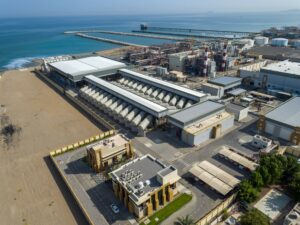
On this occasion we present the project executed for the company that operates the Al Ghubrah II desalination plant, located in the city of Muscat in the Sultanate of Oman. Our client needed a pilot plant for the testing of reverse osmosis membranes that would allow them to carry out performance tests under standard conditions, as well as washing tests, to evaluate the suitability of the chemicals used and improve the planning of the required membrane replacement.
Once the initial requirements were known, J. Huesa set to work on the design, customised manufacture, FAT tests and supply of a reverse osmosis membrane testing plant capable operating and maintaining in automatic mode the standard test conditions for seawater osmosis membranes set at 32,000 mg/l salinity, 800 psi (55 bar) feed pressure at 25° C and 8% conversion.
All of the above parameters can be adjusted for testing at other conditions.
Panoramic view of Al Ghubrah II Desalination Plant
Pilot plant requirements
The pilot plant must be able to perform performance tests in which operating parameters such as permeate flow, rejection, pressure drop, membrane fouling, temperature, etc. can be analysed, determining the performance and lifetime of the membranes according to the manufacturer.
RO membrane performance test:
| Max. Feed Flow | 17 m3/h |
| Max. Permeate Flow | 1,5 m3/h |
| Max. Operating pressure | 800 psi |
| Feed solution | 32.000 mg/L NaCl |
| Feed temperature | 25 º C |
| pH | 8,0 |
| Recovery | 8% |
Chemical cleaning test:
| Feed presure | 4 bar |
| Feed solution | Depending on chemical |
| Feed temperature | 35-45 ºC |
| pH | 2,0 – 13,0 |
Main components of the plant
The feed water is accumulated in a 1000 liter GRP tank, which is equipped with various analytical
instruments for monitoring the operating conditions of the test, as well as prepared to adjust the temperature at the start of the test.
Cooling system
Since the operating temperature is 25ºC and the test is carried out in a closed circuit in which pumping equipment supplies energy to the system, it is necessary to install a cooling system that can adapt the temperature to that required for the start of the tests and additionally maintain the temperature stable during the entire operation process.
To resolve this issue, a cooling system has been installed consisting of the following elements:
- 35 kWt chiller integrated in the main process line, in charge of keeping the temperature stable at maximum operating conditions.
- 8 kWt chiller integrated in a recirculation system on the tank to adjust the start-up temperature by means of a plate heat exchanger and to serve as a backup for the main chiller.
Once the temperature transmitter displays the set value, the test process can be started.
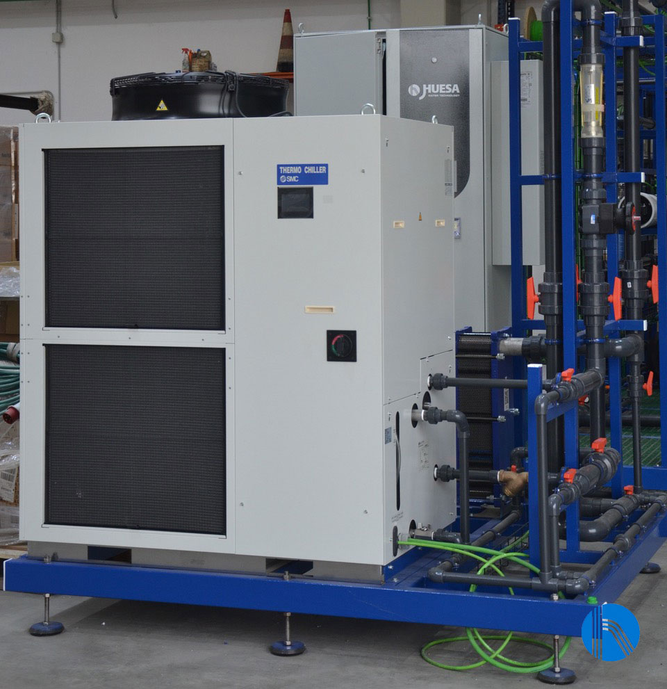
Detail of the main cooling machine
Pumping and pre-filtration systems
Given the conditions of the project for the feed pump, we have opted for a centrifugal pump made of
stainless steel that drives the tempered feed water to the high-pressure pump, previously passing
through two cartridge filters of 5 and 1 micron respectively, installed in series prior to the osmosis membrane.
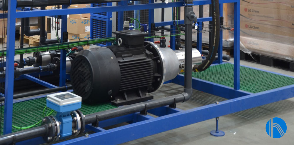
Detail of the high pressure pump
To monitor the fouling of the filters, a pressure transmitter and a pressure gauge are installed at the
inlet and outlet of each filter. The main function of these filters is to remove unwanted particles and
contaminants, increasing the service life of both the high-pressure pump and the membrane.
To ensure the correct operation of the system, a temperature transmitter, a manometer, a pH meter and
a pressure transmitter are also included upstream of the high-pressure pump. This last element is used
to detect the lack of pressure at the pump inlet, so that, if this happens, the system stops immediately
and tries to re-establish itself a defined number of times.
To ensure that salt-free water is obtained from the seawater, an alternative pressure pump has been
installed to increase the osmotic pressure, which is made of super duplex stainless steel and is
controlled by a frequency converter, so that the operating pressure can be adjusted per screen according to requirements. The operating point will be 17 m3/h at 50-55 bar.
Reverse Osmosis
Reverse osmosis is a process by which water is demineralised by pushing it under pressure through a
semi-permeable reverse osmosis membrane. It works by using a high-pressure pump to increase the
pressure on the salt side of the reverse osmosis and force the water through the semi-permeable
reverse osmosis membrane, leaving almost all dissolved salts (between 95% and 99%) in the reject
stream.
The amount of pressure required depends on the salt concentration of the input water. The more
concentrated the inlet water is, the more pressure is needed to overcome the osmotic pressure.
The installation will be provided with spiral wound polyamide membranes specially constructed for high
salt concentration water up to 8000 ppm. These membranes have a high chemical resistance, they can
work in a pH range of 2-13, which makes them very easy to wash and recover, admitting a variety of
washing chemicals.
The reverse osmosis process produces two different flows:
- Permeate water: This line is made of PVC and is equipped with analytical instruments to control
the quality of the water. - Reject line: This line is made of stainless steel and is divided into three lines:
– A line with a manual regulation valve: to regulate the rejection flow during production in manual mode.
– A line with a manual regulation valve: to regulate the rejection flow during production in manual mode.
– A line with a manual valve: to open during washing or CIP.
Both lines are mixed again with the help of a static mixer and recirculated to the feed tank.
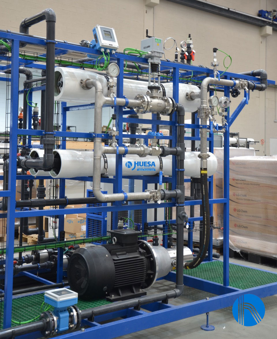
Detail of pressure bessel
CIP System
In this plant, CIP cleaning and washing is performed automatically by screen configuration and is activated manually by the operator. For this purpose, it is recommended to perform an initial rinsing process with mains water recirculating for a period of time and pouring to drain, and then refill the tank and perform the chemical cleaning of the system by adding the necessary chemicals for this purpose.
The high-pressure pump is not normally used during these processes, and is supplied with an integrated flushing valve that allows fluid to flow from the inlet to the outlet, when the pump is not running.
Instrumentation and control
The pilot plant is equipped with instrumentation and control elements (automatic valves, pressure
switches, pressure transmitters, flow meters, conductivity, and pH meters, etc.) which are centralized
in an electrical panel control, designed by J. Huesa’s Instrumentation and Control team to integrate all these signals.
The panel also includes a programmable logic controller and a touch screen for the operation and configuration of the plant, which allows to set operating parameters and monitor the plant in real time.
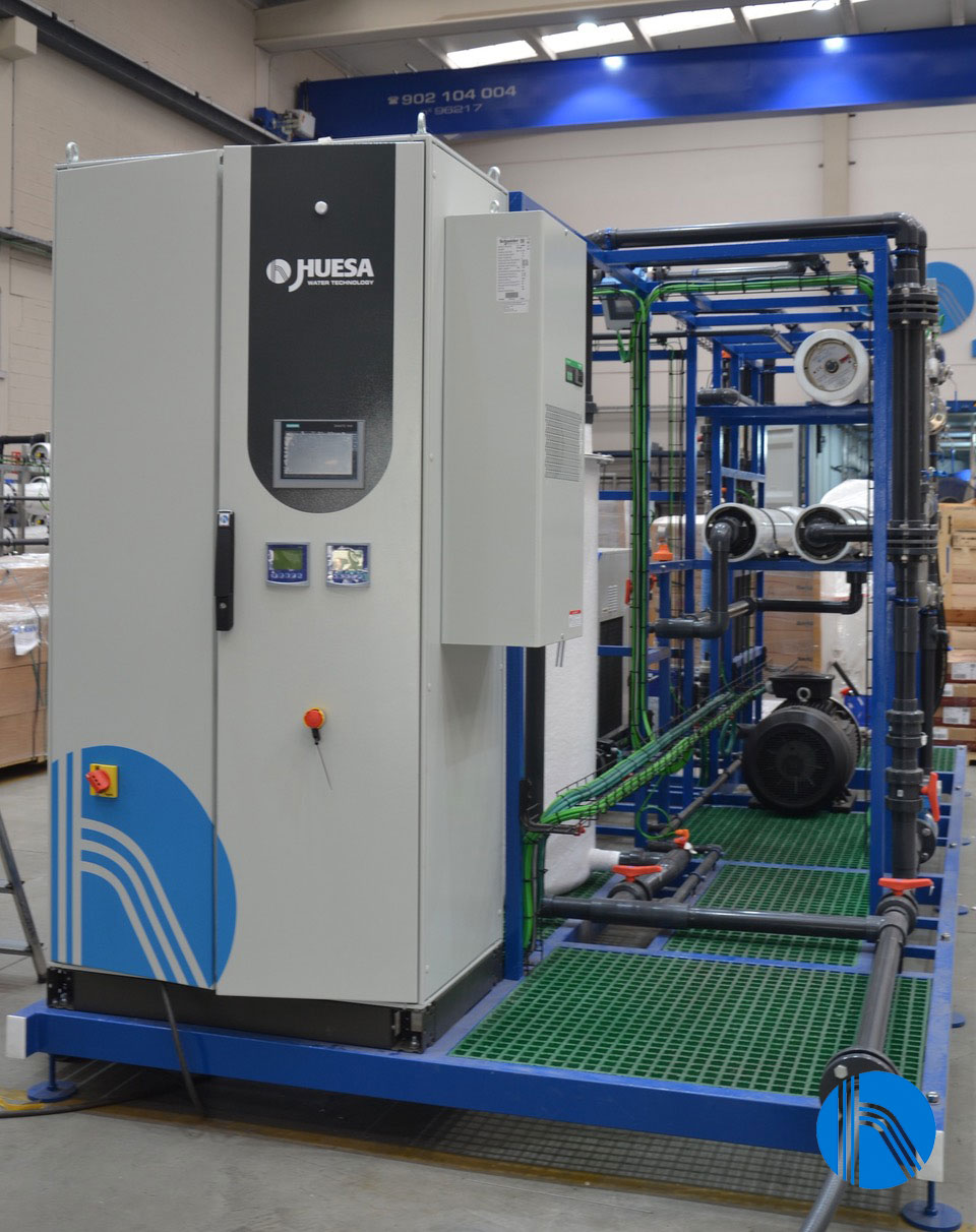
Detail of electrical panel


